Problem diagrams
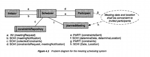
A context diagram can be further detailed by indicating explicitly which component controls a shared phenomenon, which component constitutes the machine we need to build, and which components are affected by which requirements. The resulting diagram is called a problem diagram (Jackson, 2001).
A problem diagram excerpt for the meeting scheduling system. A rectangle with a double vertical stripe represents the machine we need to build. A rectangle with a single stripe represents a component to be designed. An interface can be declared separately; the exclamation mark after a component name prefixing a declaration indicates that this component controls the phenomena in the declared set.
For example
The f label declaration states that the Scheduler machine controls the phenomena determineDate and determineLocation. A dashed oval represents a requirement. It may be connected to a component through a dashed line, to indicate that the requirement refers to it, or by· a dashed arrow, to indicate that the requirement constrains it. Such connections may be labelled as well to indicate which corresponding phenomena are referenced or constrained by the requirement.
The h label declaration indicates that the requirement appearing there constrains the phenomena Date and Location controlled by the Scheduler machine.


Post A Comment:
0 comments: